
This guide is for a set of Mikuni BDST carburettors from a Yamaha FZR400RR 3TJ1. However, it could be useful for other models that use these carburettors. When disassembling your carbs, take as many photos as necessary. Note that most parts books and manuals do not show the details of the parts and assembly of the carburettors when they are separated. Most of them will show all of the internal jets and parts, but very little of the external fittings that are between the carbs, such as springs and throttle shafts.
Removal of the throttle shafts needs to be done with great care. Because they have a long slot to hold the butterfly, they can be easily twisted or bent. Do not use the butterfly as a stop when loosening the nuts on the end of the shaft. If the butterfly screws are tight, usually because they have been staked, then first, seal the carburettor to ensure that no grit can fall into the throat, and use a Dremel or similar tool to grind away the staked section of the screw. Once the screws are removed the butterfly can be very carefully removed. Trying to force it out can damage the butterfly and the carburettor throat.
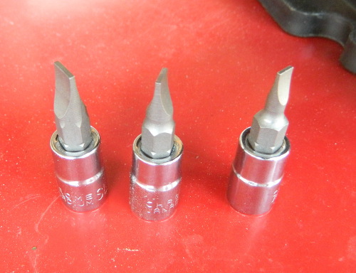
There are no phillips screws on a Japanese motorcycle, none! If you use a phillips screwdriver it will cam out and damage the screw. The screws are JIS Cross Recessed they are NOT phillips screws. You must use a JIS (Japanese Industrial Standard) screwdriver.
You must also have well fitting blade screwdrivers for the various jets. You cannot butcher your way through a carburettor.
All rubber parts, with the exception of the throttle shaft seals, should be moistened with just enough lubricant to give a glossy finish. We suggest either rubber grease or silicone (spray or grease). Never use the silicone jointing compound on a carburettor.
Orientation, for the purpose of defining left, right, and carburettors one to four, is defined as if one was sitting on the motorcycle facing forward; carburettor one, in that case, is the leftmost one. All images in this guide follow this format, so left does not necessarily mean the left side of the image but rather the left side of the carburettor as described.
This is meticulous work. You should have a clean, well lit and comfortable work area. You should also expect that small parts like springs, screws jets and washers may fall onto the floor area and that you will need to find them.
Screws and throttle shafts will need to be washed in solvent to remove any traces of oil and dirt before using thread locker.
Lubricate the threads of brass jets and screws before fitting to avoid galling and seizing. I use WD40.
- Disassembling & Cleaning
- To stake or not to stake?
- Fitting new throttle shaft seals
- Fitting the Pilot Merge Cavity Bung
- Fitting the choke plungers
- Bodies as an Assembly
- Slide & Jet Housings
- Fitting Main Jets
- Fitting Pilot Jets
- Fitting Choke Jets
- Fitting Float Assemblies
- Fitting Idle Mixture Screws
- Fitting Air Jets
Disassembling & Cleaning:
- Take photos before and as you disassemble.
- Carbs are made of an alloy with a high zinc content and they are soft. Do not use hammers or blunt objects.
- Tag and bag everything
- We have used images and details from a Keihin carb to explain the process of removing the butterfly screws because they are the most difficult.
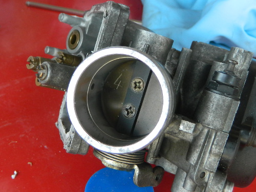 Begin by marking the butterflies. In this image I have marked cyl 4 on the bottom half of the butterfly. Now it will be possible to put it back in exactly the same position. Repeat for all butterflies. As always, take lots of pictures. |
 Even if you do not wish to stake your screws you may need to use a Dremel to grind down the staked section of screw to make it possible to remove them. For Keihins you must grind them down. Some Mikunis may come loose without having to grind. |
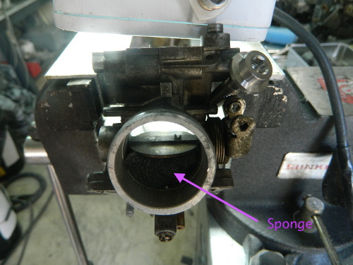 Mount the carb securely in a vice or similar, place some sponge under the butterfly, position a strong light source on the top of the carb, and lock the butterfly into a useful position to use the Dremel. Use both hands on the Dremel to avoid it kicking back. |
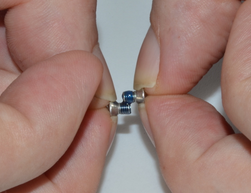
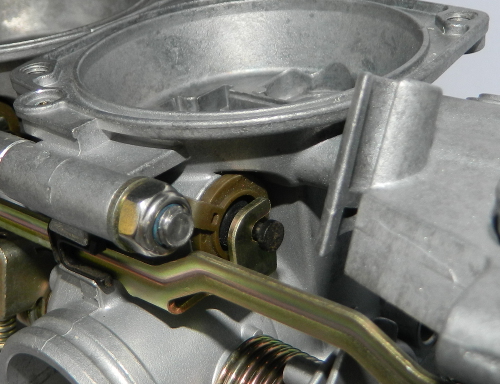
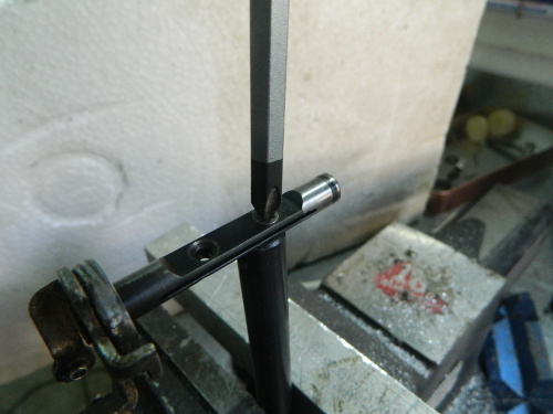 ImportantAfter grinding down the screw to be flush with the shaft, you have to support the back of the shaft with a piece of solid bar as you apply pressure and try to turn the screw. In the picture you can see how this would be done if you could rotate the butterfly sufficiently to enable your supporting rod to fit flush against the shaft. However, this is not always possible. If you have to come in at an angle then grind a profile on the end of your support bar to match the angle of the throttle shaft. Done correctly this will enable you to exert maximum downward pressure on the screws and you will be able to remove them. You have to exert a huge amount of downward pressure whilst only using a small of of rotating force. Mess this step up and you are in a very dark place. |
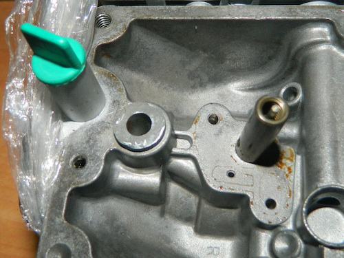
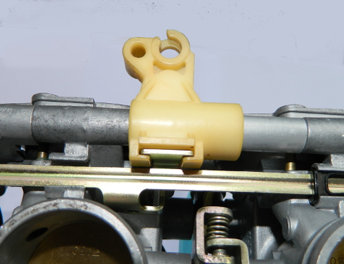
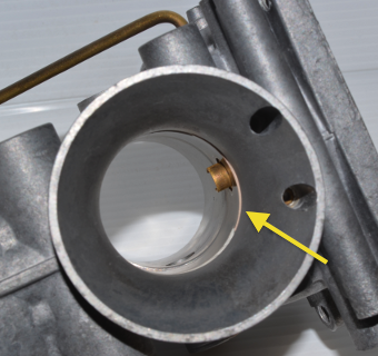
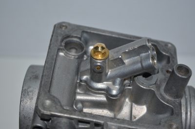
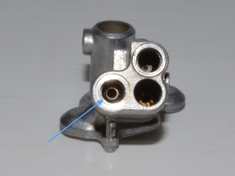
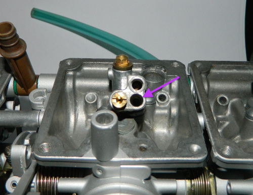
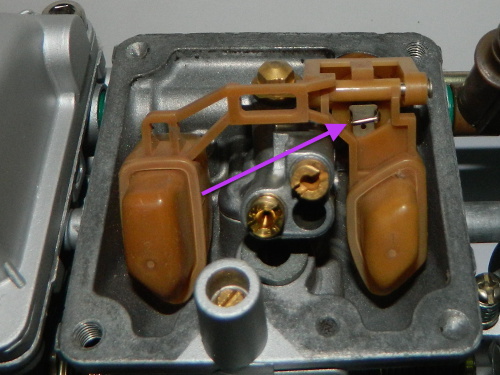
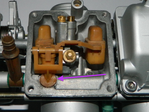
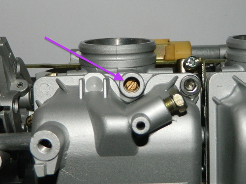
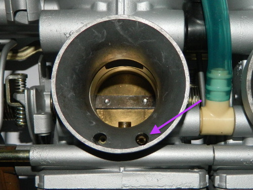
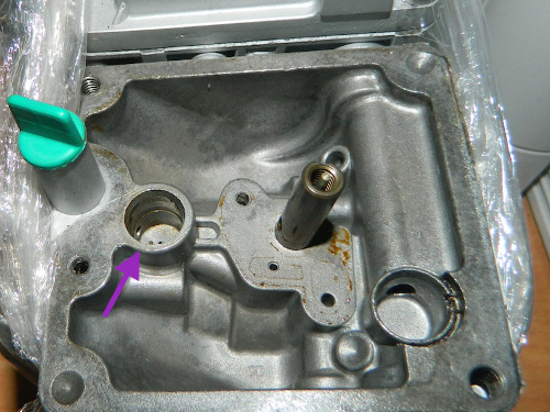 Don't forget to remove the pilot merge cavity bung.
|
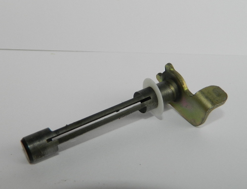
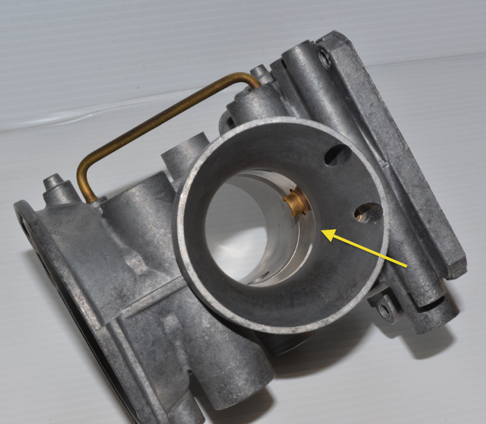
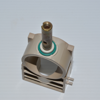
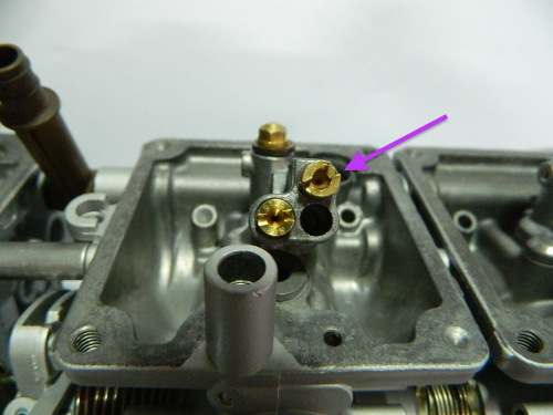
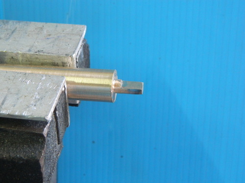 I made this tool to fit into the bung and then you can just wiggle the carb and pull at the same time to
remove the bung.
I made this tool to fit into the bung and then you can just wiggle the carb and pull at the same time to
remove the bung.
|
 Regardless of what method is chosen to clean various parts, it is important that small orifices and
jets are free of obstructions. Ultrasonic cleaning has become very popular, and is the preferred
method for cleaning of internal parts and passages.
Regardless of what method is chosen to clean various parts, it is important that small orifices and
jets are free of obstructions. Ultrasonic cleaning has become very popular, and is the preferred
method for cleaning of internal parts and passages.
|
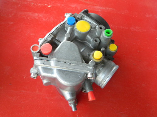 If the external body is in a very bad state you can consider blasting. But before any type of blasting
is performed, all orifices should be sealed to prevent blasting media entering the carb. You will have
to make custom blanking plates for the throat etc.
If the external body is in a very bad state you can consider blasting. But before any type of blasting
is performed, all orifices should be sealed to prevent blasting media entering the carb. You will have
to make custom blanking plates for the throat etc.
|
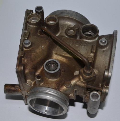
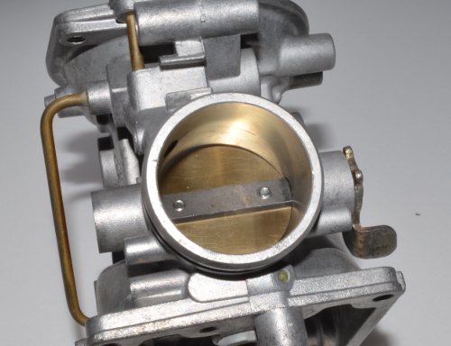
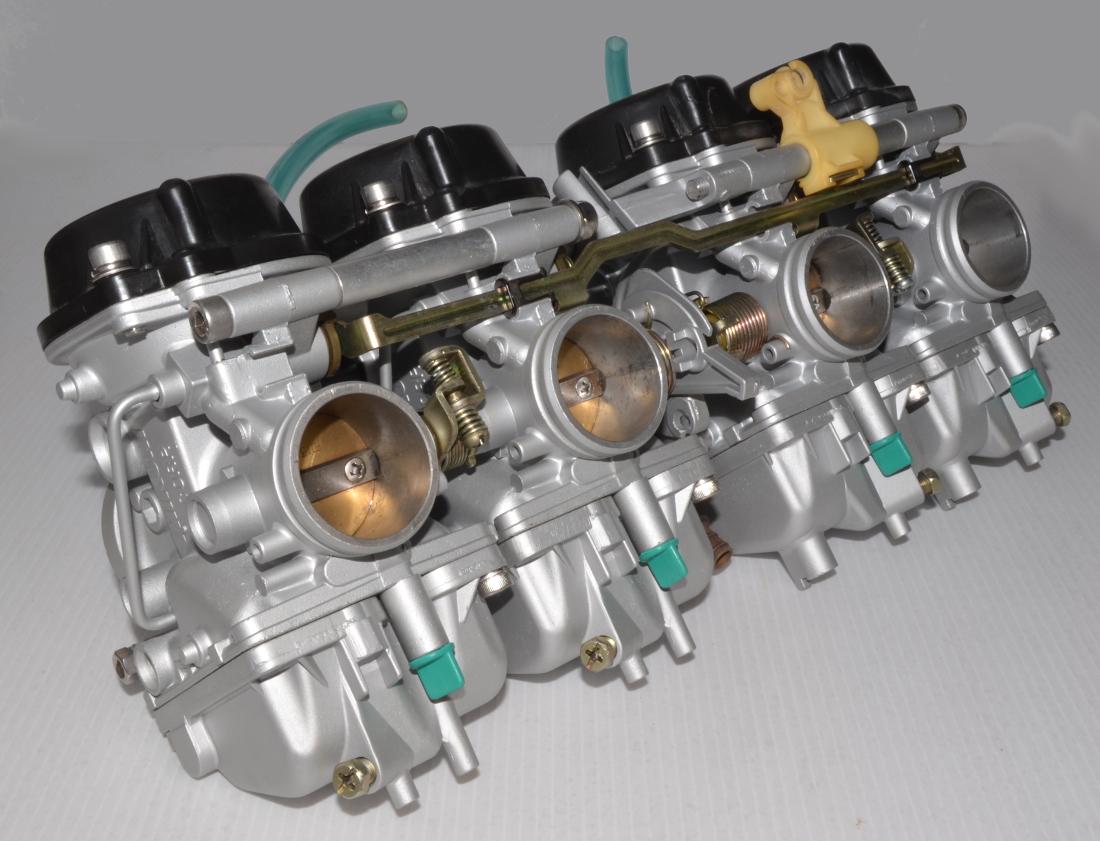
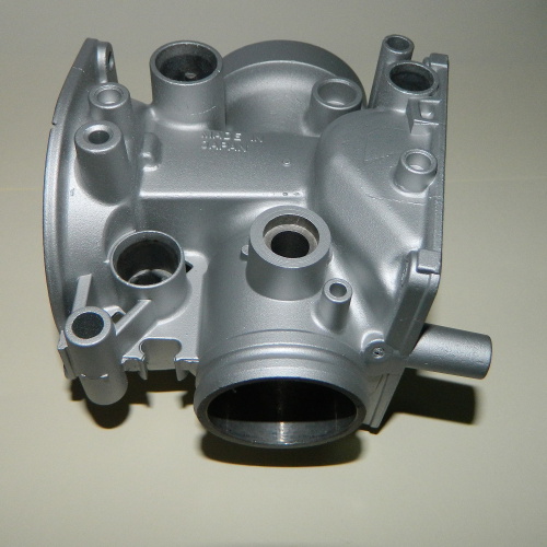 This carburettor has been ultrasonically cleaned, blasted, and then painted with a ceramic based
paint by Harper's Ultrasonic in the UK.
This carburettor has been ultrasonically cleaned, blasted, and then painted with a ceramic based
paint by Harper's Ultrasonic in the UK.
|
 If your metal parts are in a sorry state you could consider having them zinc or nickel plated.
|
To stake or not to stake?
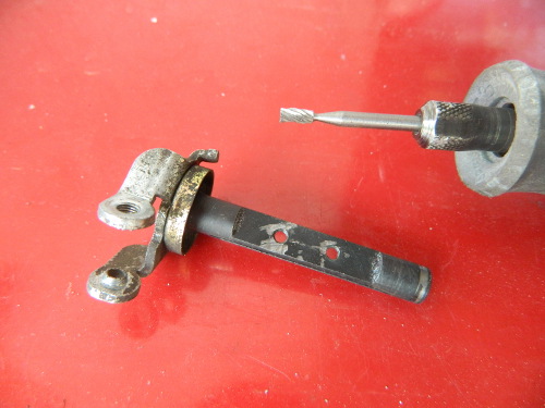
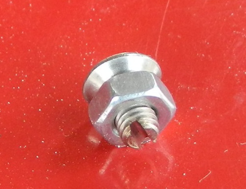 You need to keep in mind that butterfly and the throttle shaft are fragile. So the trick is to prepare the screws for staking first. Fit a nut over the screw so that you can hold it in a vice and it will also allow you chase the thread when you remove the nut. You will grind a slot in the screw with a Dremel fitted with thin cut off wheel. |
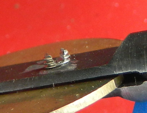 Grind the slot until it is slightly proud of the shaft. You can remove and refit the screw as often as possible to get it right. In this image I have already staked the screw and I have done it on an old shaft that is not fitted to a carb. For the real thing you must support the head of the screw from behind otherwise you will bend the shaft, remember it is fragile. |
 I used 3 sizes of 1/4 drive screwdriver blades to spread the screw. Important:Don't expect the staking to hold the screw firm. It will stop the screw from falling out and finding its way into your combustion chamber. Use Loctite and tighten firmly. |
Important:I strongly recommend that you do not use cheap M3 screws from your local supplier. They are far too weak to be trusted for this application. Which is the reason why we use and supply stainless steel. |
Fitting new throttle shaft seals.
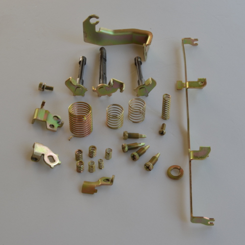
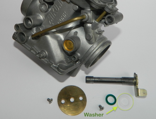 Parts to be used for carburettor 4. |
 Some steel wool can be used to clean up the butterfly. |
| Important: Before fitting the seal do a mock assembly of the washer, shaft and butterfly to ensure that everything fits and seals as it should. | |
 Note: The seal is fitted, what appears to be, backwards. Do NOT use grease on this seal. |
 Fit the thin plastic washer onto the throttle shaft and gently slide into the housing (the LiteTek part is made from Teflon). You can lubricate the shaft but avoid getting any lubricant in the butterfly screw threads. |
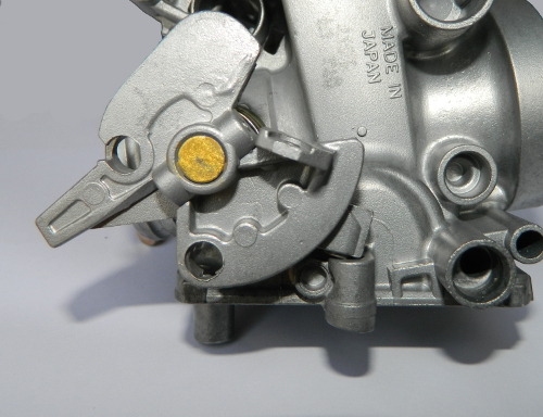
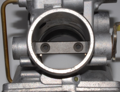 This is the correct positioning of the throttle shaft in the closed position. The actuating tab faces forwards, as does the countersunk portion of the throttle shaft screw holes. |
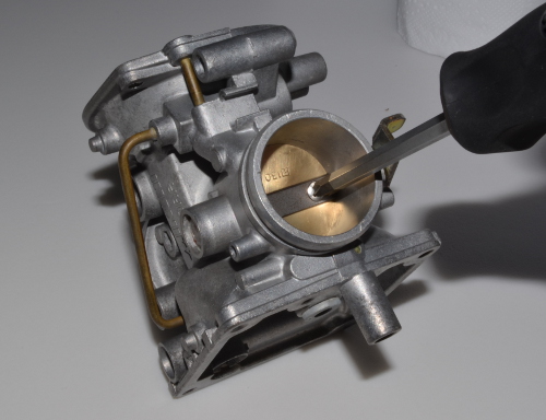 Gently fit the throttle butterfly into the throttle shaft. Important:Fit the screws loosely and keep moving the butterfly until it makes a good seal with the throttle closed. Hold the carburettor throat up to a strong light to check that a good seal is made. When you are satisfied with the position of the butterfly tighten the two screws, not fully, and check again. |
 You will need some threadlocker. These screws are stainless steel so consult the appropriate technical documentation to determine if you need to use a primer. Remove one of the screws so that you can apply threadlocker to the thread. Also takes steps to ensure that the threadlocker has not spoiled. Most of these products have a limited shelf life and should be stored in a cool location. |
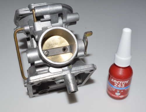
 It is important to only apply the threadlocker to the thread and ensure that you do not spread over the countershaft part of the screw. I usually use another screw to roll the threadlocker around the thread ( fortunately all LiteTek kits come with spare screws). Any excess can be wiped off with a cotton tip. |
|
Fit the screw, tighten firmly and repeat the process with the other screw. |
 Check that your throttle butterfly rotates freely. |
 This is carburettor 1. Follow the same sequence as that of carburettor 4. |
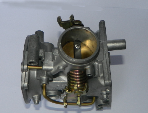
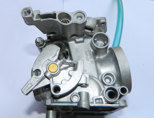
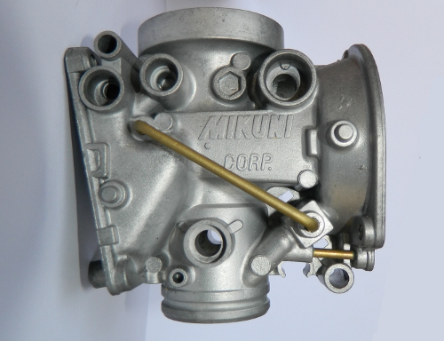 This is carburettor 3. It can be easily identified because the brass choke tube is straight and the throttle shaft bore is open at both ends. |
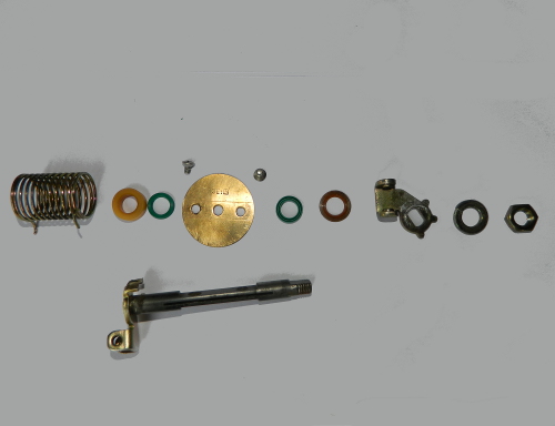
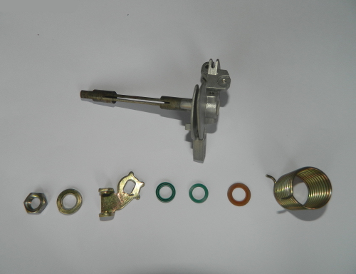 Parts to be used for carburettor 3. |
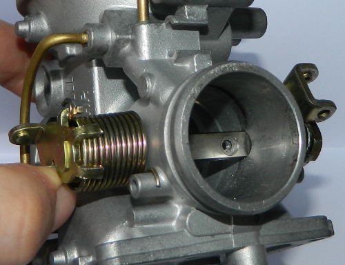
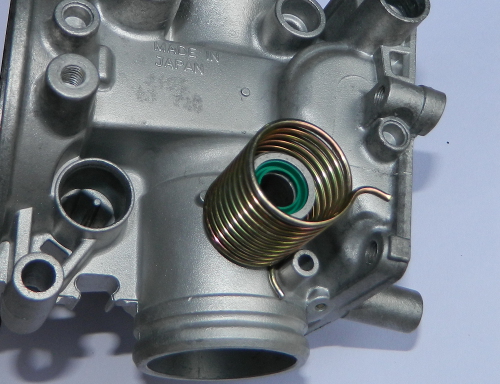 After fitting the two throttle shaft seals. Sit the throttle return spring on the carb. Note the gentle curve on the spring tangs that distinguish this spring from the one that is used on carburettor 2. |
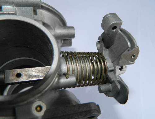 Gently slide the throttle shaft into the carb and ensure that the spring picks up on the locating cylinder. Do not push the shaft all the way in yet. |
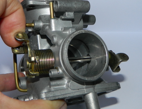
 Rotate the shaft in an anti-clockwise direction until the throttle stop tab has moved past the stop on the carb body. Then push the throttle shaft all the way through. |
 Ensure that the return spring is fully seated. |
 Fit the thin nylon washer to the other end of the shaft. |
 Then fit throttle plate as per the image, spring washer and nut. Then tighten with a 12mm socket. Do NOT use the throttle butterfly as a stop to tighten the nut against because this could easily bend the throttle butterfly. |
 Repeat the steps to fit the throttle butterfly as per carburettor 4. |
 Parts to be used for carburettor 2. |
 Fit both throttle shaft seals. |
 Thick nylon washer fits to the right side. |
 Fit spring so that it clips on the tang as shown in the image. The other two tangs will place more tension on the spring and make the throttle stiffer. |
 Thin nylon washer fits to the other side. |
 This picture shows the throttle shaft rotated to the throttle closed position. Fit the left hand tang so that it faces forward whilst the right hand tang, with the spring, faces rearwards. Then fit the spring washer and nut. |
 Rotate the throttle shaft a further 90 °. Now the butterfly can be fitted. |
 With the butterfly fitted and the throttle closed, the correct positioning of the tangs and spring can be seen. |
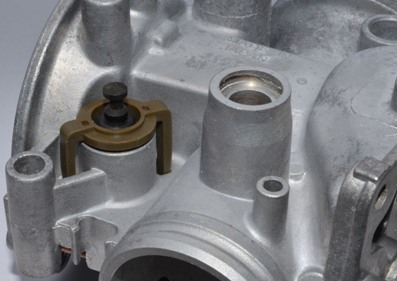
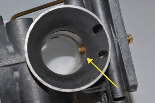
Fitting Pilot Merge Cavity Bung:
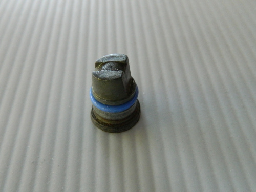
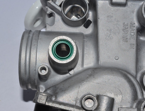
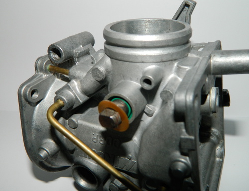
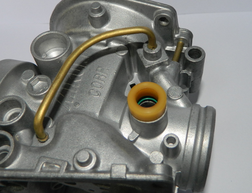
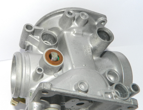
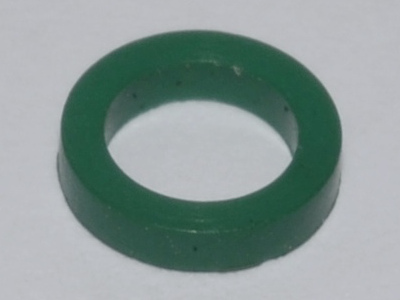
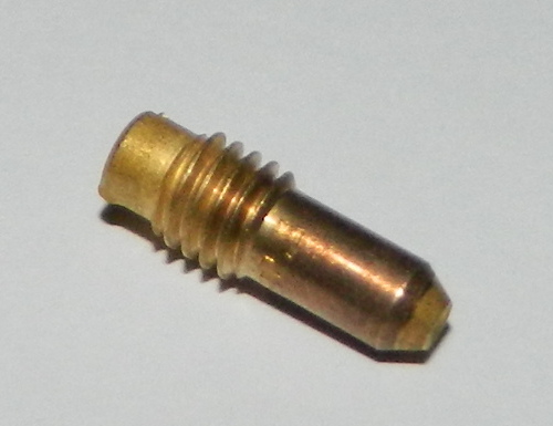
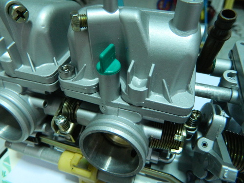
Lubricate the new o-ring with some rubber or silicone grease. Just enough to make it glossy. Note: This o-ring is not shown in parts books, nor is it included in other carb kits. |
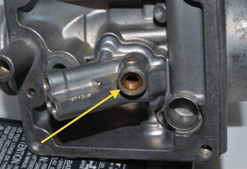
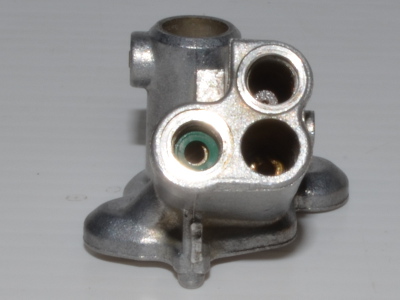
 Then align the flat on the bung with that in the cavity and press home
|
Fitting Choke Plungers:
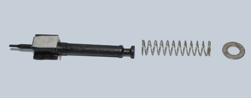
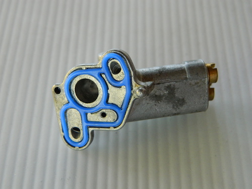
1/ Plunger assembly components. |
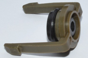
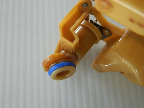
2/ Lubricate new seal with silicon and fit to clip. |
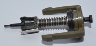
3/ Push plunger through seal. |

4/ Take note of this slot. |
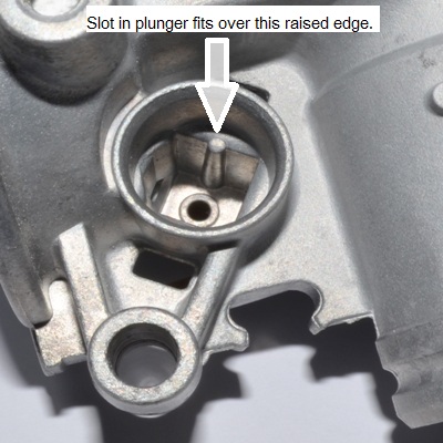
5/ It aligns here. |
6/ Push the clip home and then ensure that the plunger moves freely up and down. Repeat for all carbs. |
Bodies as an Assembly:
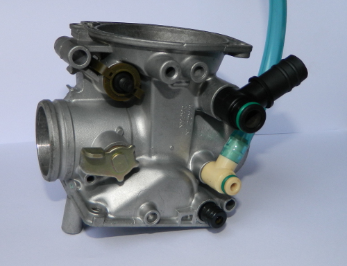
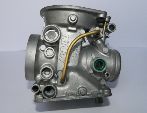
This is carburettor 4 and to be assembled with carb 3. Lubricate new seals and o-rings and fit to vacuum breather, float bowl vent breather and fuel tube. Then assemble as shown. |
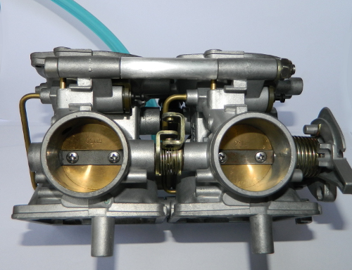
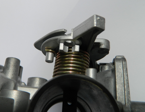
Fit the spring between the two throttle shafts as shown and then fit the bolt, spacer, washer and nut that secure the two carb bodies together. |
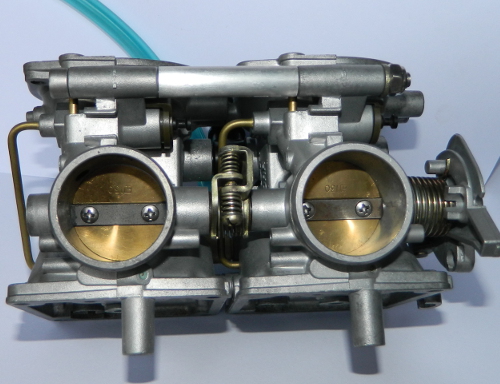
Fit synchronisation screws and two springs as shown. The adjustment screw is passed through the thicker spring. |
 Now fit the throttle cable bracket. The screw is M5 * 18. |
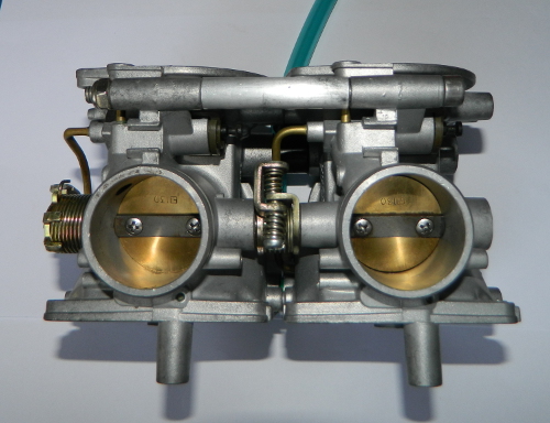 Fit carbs 1 and 2 together as per 3 & 4. Temporarily fit the long M6 bolt to hold the assembly together. |
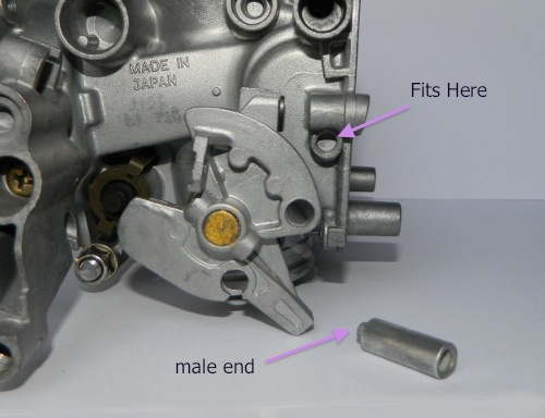
This spacer has a male and female end and is located as shown. |
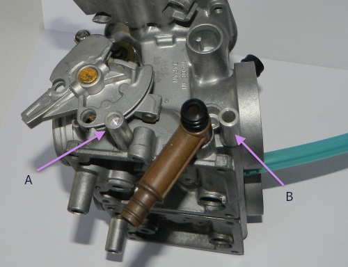
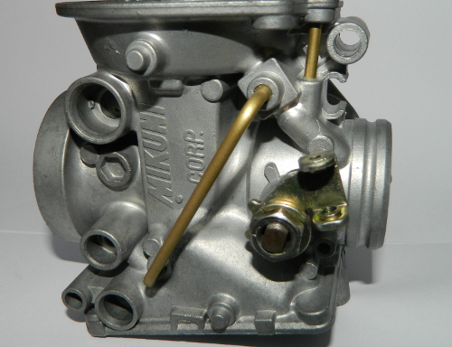
Fit the two fuel seals to the centre fuel tee and assemble as shown into carb three. For this motorcycle there are two spacers, marked as spacer A & B in this image. Spacer B is a distance tube for the long 5mm bolt that passes through the entire four carburettors and can be easily fitted as the bolt is positioned. |
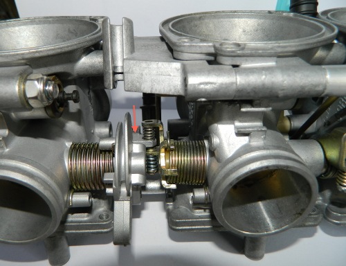
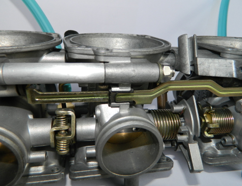
1/ Remove the nut that is temporarily holding carbs 1 & 2 together and the fit carb assembly 1 & 2 to assembly 3 & 4. Then fit the long bolt that passes through all four carbs and partially tighten the nut. 2/ Refit the bolt that holds carbs 1 & 2 together. 3/ In order to fit the centre spring, first rest it on the flat section that is pointed to in the image. Then use a small screwdriver to compress it and push it sideways into location with your finger. 4/ Now fit the synchronisation screw and spring. |
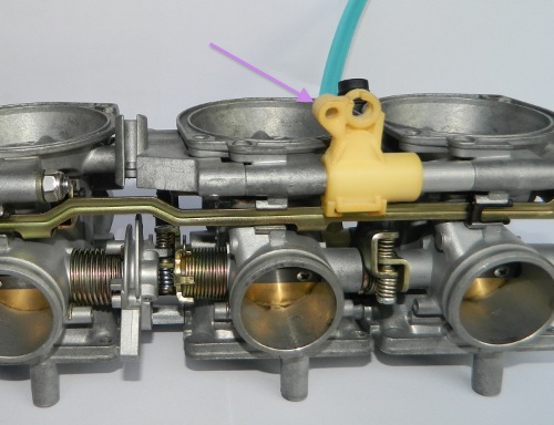
1/ This is the choke actuating slider. I did not fit it previously as I did not want it to make assembling the four carbs any more awkward than it already was. 2/ Remove the bolt that holds carbs 1 & 2 together and fit as shown in the image. |
Fit the two plastic choke bar bushes as shown. |
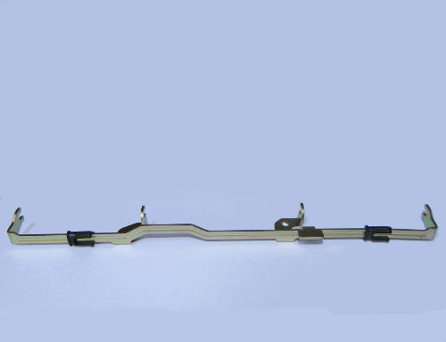
There are two parts to fitting the choke bar and they are done at the same time. This image shows how the bar connects to the slider. |
The four tangs are simultaneously fitted over the choke plungers. |
Now squeeze the tips of the bushes together and slide into the housings. |
Slide & Jet Housings:
 1/ Before beginning the assembly, trial fit the slide housing. without an o-ring, into the carb body to take note of how well the slide housing aligns with the carburettor throat. |
|
2/ Fit the slide housing o-ring (OR-018) to the underside of the slide housing. Note: That o-ring is not shown in many parts books. |
3/ Now, with the o-ring fitted, the slide housing is no longer sitting flush. This is because of the thickness of the o-ring which needs to be compressed. These parts have been designed by Mikuni to allow for the correct amount of compression to be applied to the o-ring, and it is very important that the correct size and thickness of o-ring is used. Choosing a 10 x 1mm, or 10 x 1.5, the common metric sizes, because it is "close enough" is incorrect and will result in an inadequate seal or mis-aligned slide housing. |

4/ Because the recess for the seal is quite shallow, you may have difficulty getting the seal to remain in the groove when fitting. Therefore we recommend to use Permatex #85420 fuel resistant gasket cement. Apply the smallest amount needed to a few spots on the jet housing side of the seal. ONLY ON ONE SIDE |
5/ Fit the jet housing seal (JH-001) to the jet housing. |
 6/ Fit the jet housing over the needle jet and against the body. The needle jet sits well below the lip of the jet housing. This means that the brass screw and washer that are used to secure it cannot be be firmly tightened. As the screw is tightened it compresses both the slide housing o-ring and the jet housing seal. |
7/ Brass screw and washer. Check that the surfaces of the washer are smooth and clean. |
8/ Press down hard on the top of the slide housing and then gently tighten the needle jet screw (6mm hex) until the slide housing is flush with the throat and the screw feels snug. Don't rely on the screw to pull the slide housing home. Since it is hollow it can easily break. |
|
Fitting Main Jets:
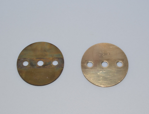
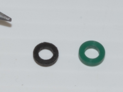 1/ On the left is the standard Yamaha main jet square ring. It is a new part. On the right is the LiteTek part made from Viton 75. |
2/ Because of the very small size, the standard Yamaha part does not handle the heat involved in the manufacturing process very well. |
3/ The LiteTek part, being made from Viton, is far more heat resistant resulting in a better quality product. |
4/ This is where we fit the square ring. |
5/ Fit the square ring into the main jet recess. |
6/ The main jet screws down and compresses the square ring. Note: Some motorcycles do not use the same size main jet for each cylinder. Consult your workshop manual or parts book. |
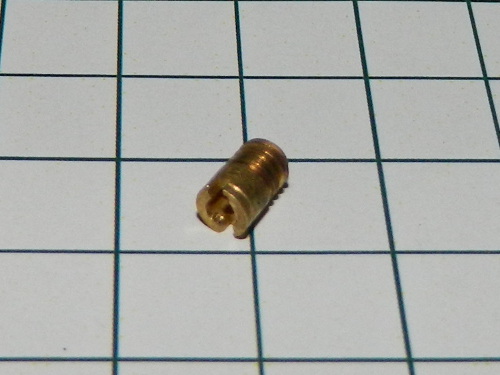
Fitting Pilot Jets:
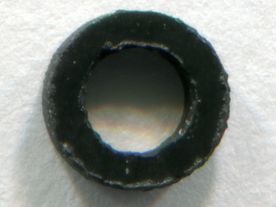
This is a pilot jet. Note: There are several types of Mikuni pilot jets. |
 The pilot jets locate next to the main jets (this may vary according to your carburettor model). They screw quite deeply into the hole. Do not over tighten these small brass parts as they can be easily damaged. |
Fitting Choke Jets:
This is a choke jet. They are actually identical to the main jets but just a smaller orifice. You can see that the screwdriver slot of this one has been damaged in the past. This is what occurs when not using the correct tools. |
Fitting Float Assembly
Fit the o-ring to the float needle seat. |
Fit the float needle into the seat and ensure that the wire clip goes over the float tang. |
Press the float assembly into the body. On some FZR250's there seems to be an issue of the o-ring being too loose and some owners have said that it is too tight and tends to pop out. Do not be concerned. The assembly is held in place by the float bowl. |
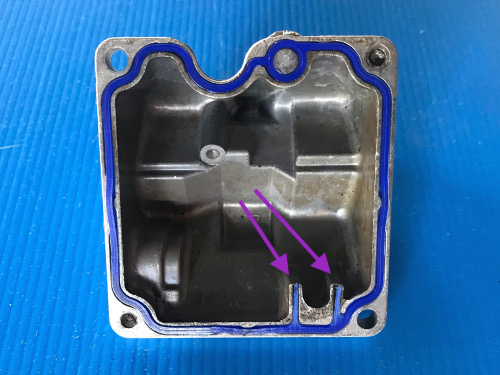
Fit the float bowl seal to the float bowl. The two rubber tangs that are arrowed are important to ensure the the float assembly is pressed home correctly. Without them the float assembly would be free to slip out of the carb body an amount equal to the compressed float bowl seal. If you are not going to use the carburettors immediately you should lubricate the inside of the bowls and the bodies with WD40 or similar to prevent corrosion. |
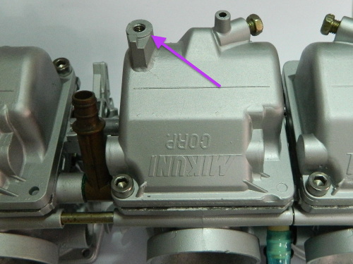
Fit the float bowls and take note that some of them may have lugs to hold idle adjust cable brackets etc. Refer to the photos that you took before disassembly. |
Fitting Pilot Mixture Screws
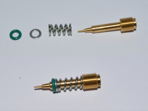
Fit the spring, washer and o-ring as shown. Chamfered side of washer towards o-ring. |
Fit the screws and gently tighten until they seat. Then turn out the number of turns as specified in your service manual. If you here a squeaking sound then you have obviously not lubricated the threads. Kill yourself immediately. |
Ducati owners can fit the dust caps. |
Fitting Air Jets:
This is an air jet. |
It fits to the right hand opening. As always, lubricate the thread first. |
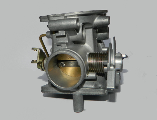
Assembled
|