
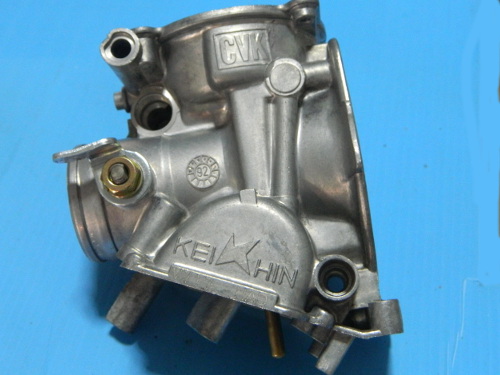
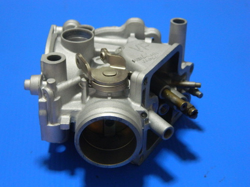
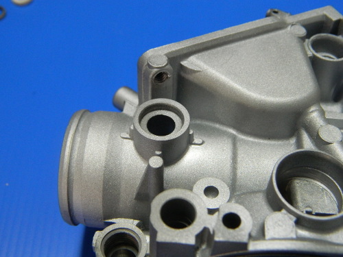
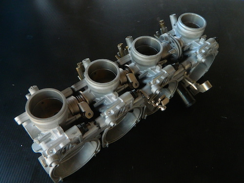
This guide is for a set of Keihin carburettors from a Honda CBR250RR MC22. However, it could be useful for other models that use Keihin carburettors. When disassembling your carbs, take as many photos as necessary. Note that most parts books and manuals do not show the details of the parts and assembly of the carburettors when they are separated. Most of them will show all of the internal jets etc, but very little of the external fittings that are between the carbs, such as springs and throttle shafts.
Throttle Shaft Seals - Replace or Not?
|
There seems to be a bit of a controversy as to whether one should replace the throttle shaft seals. First of all, the premise that you never have to replace them is nonsense. If that were the case, then why did the engineers who designed them, insist on fitting them in the first place? So all of the internet opinion pieces need to be seen in that context. Do you need to replace them? Well if they are not leaking, then no you don't have to, but you must consider how long they are going to last. How old is your motorcycle? How many times do you want to do this job? Personally, I like to do it once and do it right. The other popular theory is that you can't remove the throttle shafts, more nonsense. There maybe some motorcycle carburettors where this is true, but for most, if you can remove the butterfly screws then you can remove the shafts. |
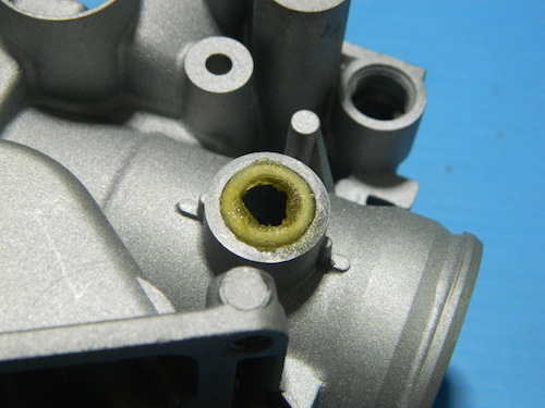
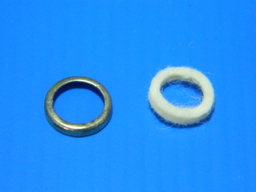
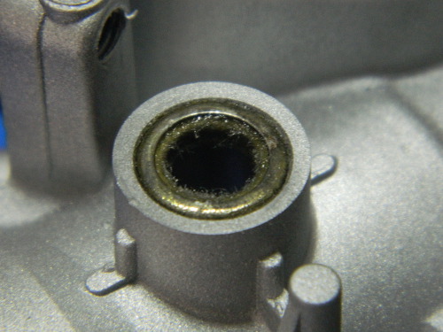
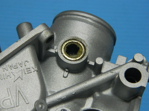
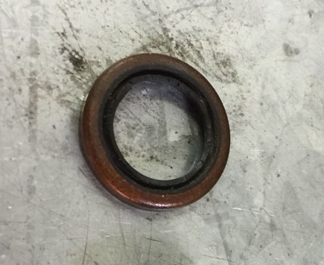 This is a leaking OEM seal removed from a Keihin carburettor.
|
Warning: Twisted Shafts & Bent Butterflies
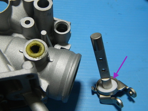
Removal of the throttle shafts needs to be done with great care. Because they have a long slot to hold the butterfly, they can be easily twisted or bent.
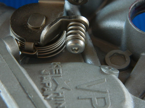
The most common cause of this is trying to loosen the nut on the end of the shaft. This can not only twist the shaft but also bend the butterfly. To loosen the nut you must stop the shaft from rotating by securing the throttle lever tang. There is no other way. I prefer to remove the butterfly first, so there is no risk of it being bent. However, once this is done the shaft is even more vulnerable to twisting. If you leave the butterfly in then it must not be in the closed position when you try to loosen the nut. You must also support the throttle shaft from behind when loosening or tightening the butterfly screws. You must prepare the tools you need first.
LiteTek Throttle Shaft Seals:
Keihins use both felt and bonded steel-rubber throttle shaft seals, We have produced two thicknesses of the felt seals because one of the seals has a deeper housing that can facilitate this. More seal means greater durability. The outer seals, on carbs 1 & 4, are rubber bonded to a steel shell. Unfortunately, Keihin have staked the housing after fitting, a really dumb idea, which means that it is next to impossible to be certain of being able to successfully fit new ones. In some cases you could grind the housing circular again but in others the distortion is too great.
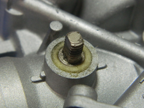
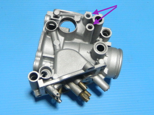
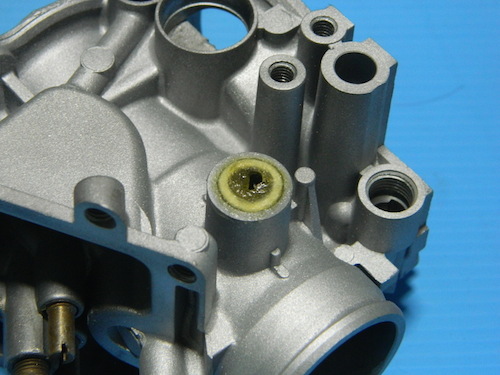
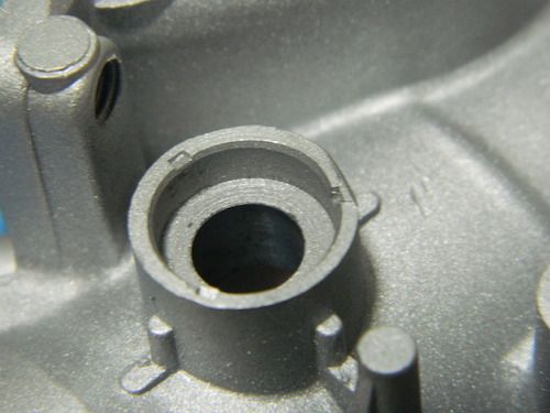 The housing has been staked by the nice people at the Keihin factory. Not because they are stupid, oh no, this is deliberate. They just don't want you reconditioning their 30 year old carburettors. If they did then they would sell the parts (never going to happen). You have to restore this to a round hole before fitting the seal or you will never get it in. That is always going to be a risky proposition. |
 After experimenting with some OEM style seals, we have decided to abandon the idea of offering that
solution. Instead we have designed a full rubber seal, made from FKM which is commonly known by the
trade name of Viton. This makes it very easy to fit new seals and they could even be installed without
removing the shaft. These seals are modelled on the Mikuni versions of the same part.
After experimenting with some OEM style seals, we have decided to abandon the idea of offering that
solution. Instead we have designed a full rubber seal, made from FKM which is commonly known by the
trade name of Viton. This makes it very easy to fit new seals and they could even be installed without
removing the shaft. These seals are modelled on the Mikuni versions of the same part.
|
Tools:
- There are no Phillips screws on a Japanese motorcycle, none! If you use a Phillips screwdriver it will cam out and damage the screw. The screws are JIS Cross Recessed they are NOT Phillips screws. You must use a JIS (Japanese Industrial Standard) screwdriver.
- You must also have well fitting blade screwdrivers for the various jets. You cannot butcher your way through a carburettor.
- If removing the throttle shafts you will need a Dremel or similar.
- You will also need a loupe or similar to be able to examine the intricate passages and parts
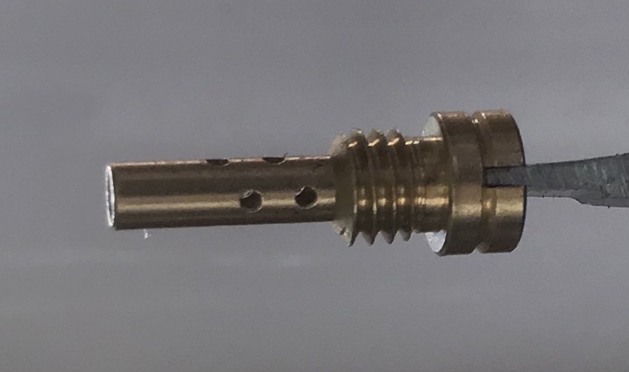
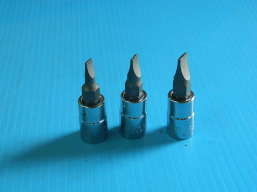
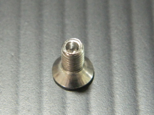
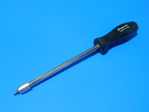
Don't bother with over the counter blade screwdrivers. They are useless rubbish. Buy some new ones then grind and file them to be a perfect fit. Here is one I did for Keihin pilot jets.
Lubricant & Threadlocker:
- All rubber parts, with the exception of the throttle shaft seals, should be moistened with just enough lubricant to give a glossy finish. We suggest either rubber grease or silicone (spray or grease). You can use silicone jointing compound to bond the rubber throttle shaft seals into their housings but no where else.
- Lubricate the threads of brass jets and screws before fitting to avoid galling and seizing. I use sewing machine oil
- Screws and throttle shafts will need to be washed in solvent to remove any traces of oil and dirt before using thread locker.
Orientation:
-
For the purpose of defining left, right, and carburettors one to four, left is defined as if one was sitting on the motorcycle facing forward; carburettor one, in that case, is the leftmost one. All images in this guide follow this format, so left does not necessarily mean the left side of the image but rather the left side of the carburettor as described.
Warning:
- This is meticulous work. You should have a clean, well lit and comfortable work area. You should also expect that small parts like springs, screws jets and washers may fall onto the floor area and that you will need to find them.
- You will need sealable containers to keep the various parts in.
- If the following guide makes it look so easy then I have done my job. But the truth is that it is not easy at all. If you are determined to conquer this task then I suggest you buy a used set of carbs in the worst condition you can and as cheaply as possible. Learn on them first.
Dowels, dowels, dowels and dowels. These things are an absolute pain in the arse. Yes, Mr Keihin we get the idea, but the road to hell is paved with good intentions. These parts are exposed to the environment, not inside a nice oily engine. If the dowels have suffered any corrosion at all it is going to make it difficult to get your carbs apart. You may need to soak them for a while and be patient.
- Take photos before and as you disassemble.
- Carbs are made of a very soft alloy, so do not use hammers or blunt objects against the alloy parts
- Tag and bag everything
- We can skip all the mundane details of taking the carbs apart. If you read through this guide carefully you will know how to take them apart.
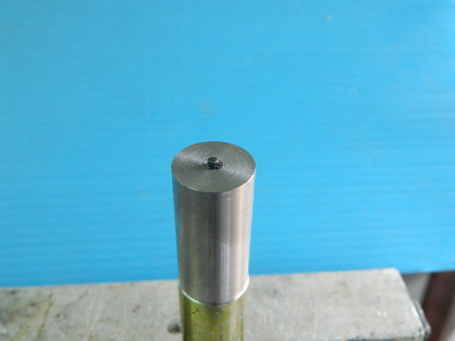
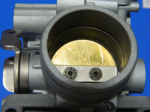
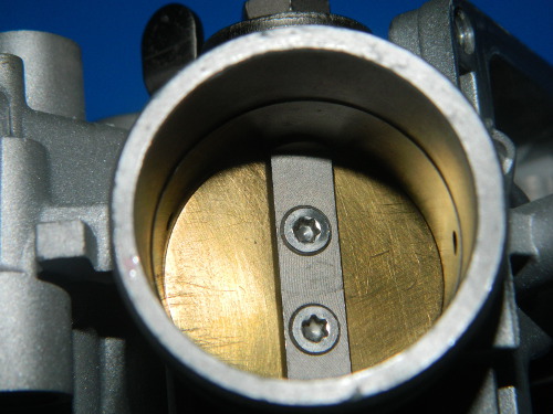
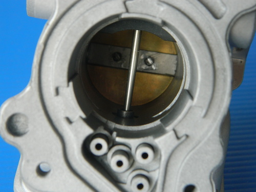
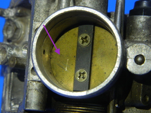 When you are ready to remove throttle shafts, it is imperative that you remove the butterflies first. You must remove the butterflies before trying to remove the throttle shaft nuts. This is because the butterflies and shafts are very fragile and will bend easily. Begin by marking the butterflies. In this image I have marked a 4 (for cylinder 4) on the bottom half of the butterfly. Now it will be possible to put it back in exactly the same position. Repeat for all butterflies. As always, take lots of pictures. |
 Even if you do not wish to stake your screws you have to use a Dremel, or similar tool, to grind down the staked section of screw to make it possible to remove them. Some Mikunis may come loose without having to grind. ImportantYou have to grind them all the way down. Don't leave any part of the screw protruding. |
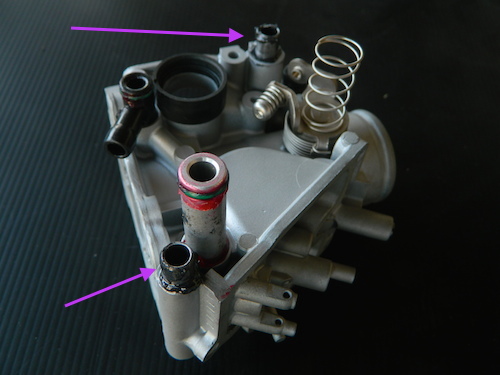
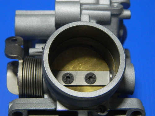
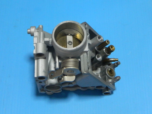
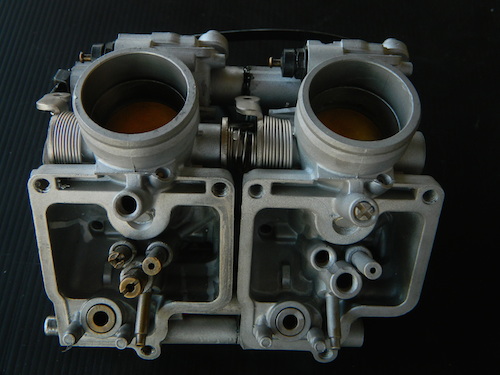
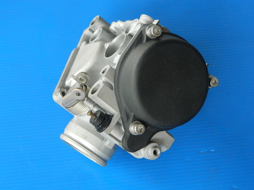
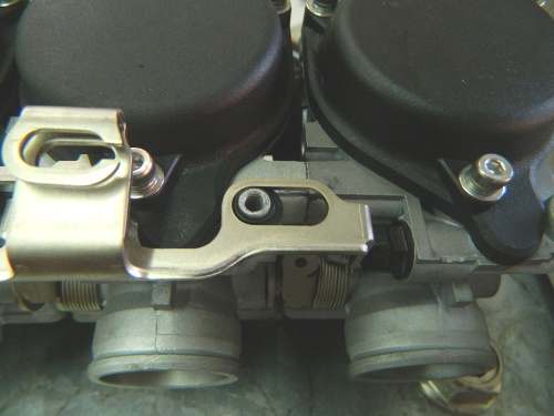
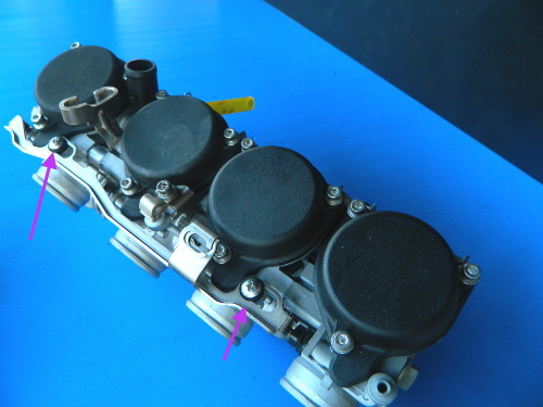
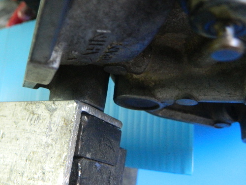 Mount the carb securely in a vice or similar. In this image you can see the carb is clamped between the two vent housings. If your carbs do not have a parallel flat surface then you need to find an alternative way to hold them securely. |
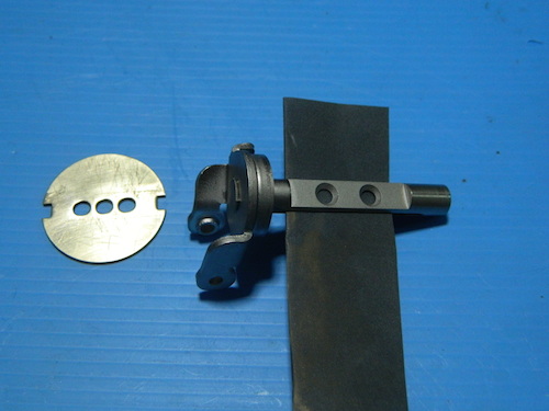
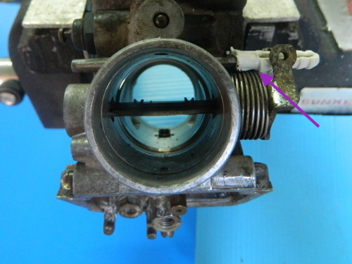 The next step is to fix the butterfly into a position where you can best grind away the screws. I used a plastic wall plug. |
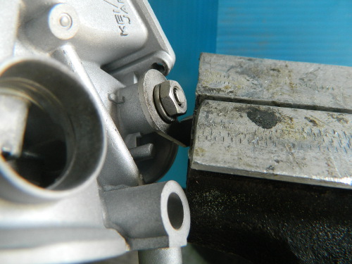
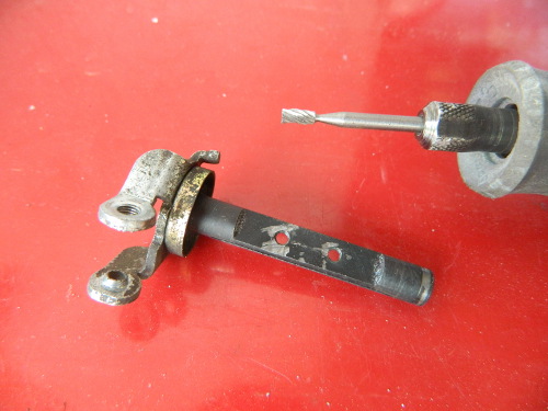
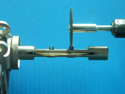
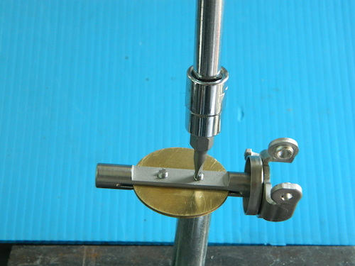
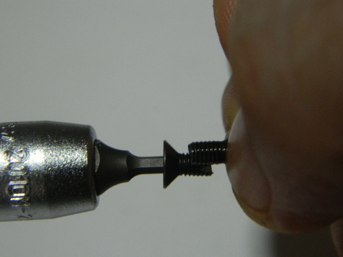
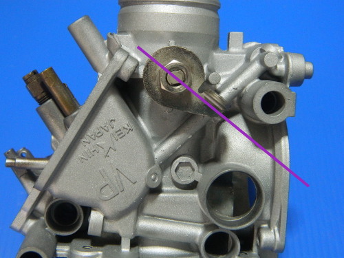
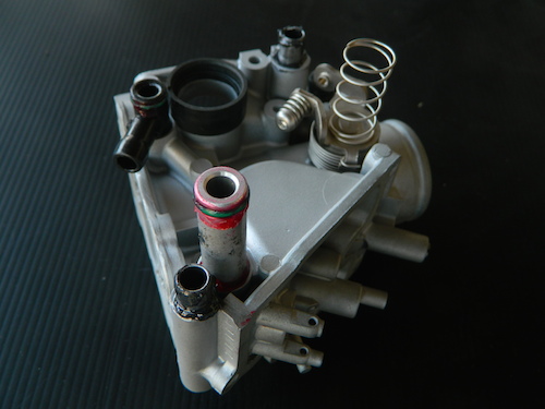
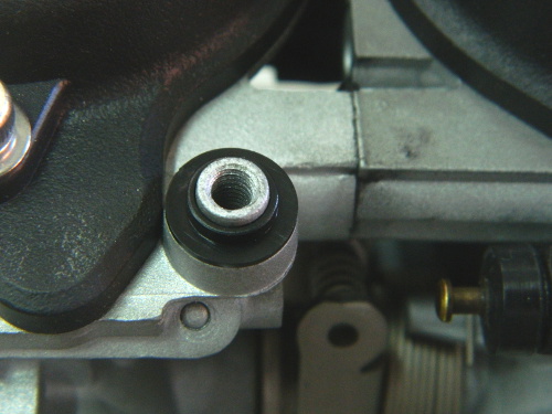
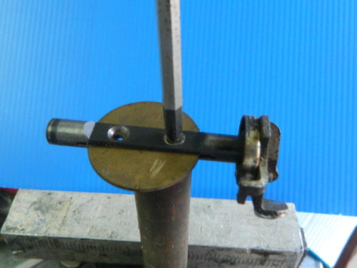 ImportantAfter grinding down the screws, you have to support the back of the shaft with a piece of solid bar as you apply pressure and try to turn the screw. This picture is just to show how that looks so you have to imagine that the carb is invisible and you will get the idea. Done correctly this will enable you to exert maximum downward pressure on the screws and you will be able to remove them. You have to exert a lot of downward pressure whilst only using a small amount of rotating force. Mess this step up and you are in a very dark place. |
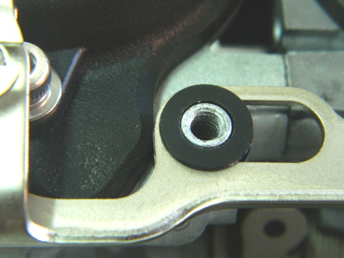
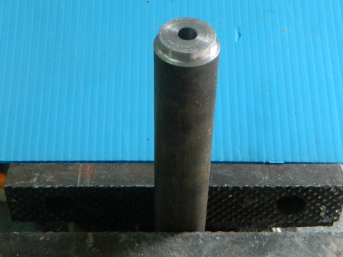 The support bar, let's call it Support Bar 1, is just a piece of steel rod with a hole in the end. The hole is not needed for the previous step but will be needed later. |
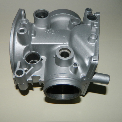
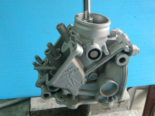
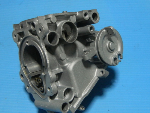
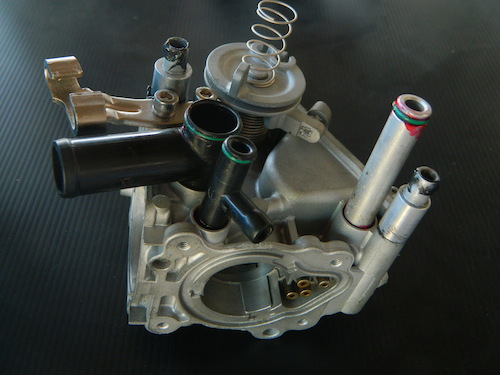
 Regardless of what method is chosen to clean various parts, it is important that small orifices and
jets are free of obstructions. Ultrasonic cleaning has become very popular, and is the preferred
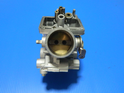
method for cleaning of internal parts and passages. This carb was cleaned with ThreeBond Engine
Conditioner and then finished in a small home ultrasonic cleaner. It looks like a new part.
Regardless of what method is chosen to clean various parts, it is important that small orifices and
jets are free of obstructions. Ultrasonic cleaning has become very popular, and is the preferred
method for cleaning of internal parts and passages. This carb was cleaned with ThreeBond Engine
Conditioner and then finished in a small home ultrasonic cleaner. It looks like a new part.
|
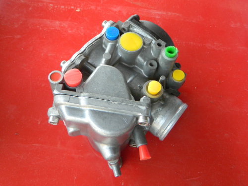 Another option is blasting but before any type of blasting is performed, all orifices should be sealed
to prevent blasting media entering the carb.
Another option is blasting but before any type of blasting is performed, all orifices should be sealed
to prevent blasting media entering the carb.
|
 This Mikuni carburetor has been ultrasonically cleaned and painted with a ceramic based paint by
Harper's Ultrasonic in the UK.
This Mikuni carburetor has been ultrasonically cleaned and painted with a ceramic based paint by
Harper's Ultrasonic in the UK.
|
 If your metal parts are in a sorry state you could consider having them zinc plated
|
 ... or nickel plated.
|
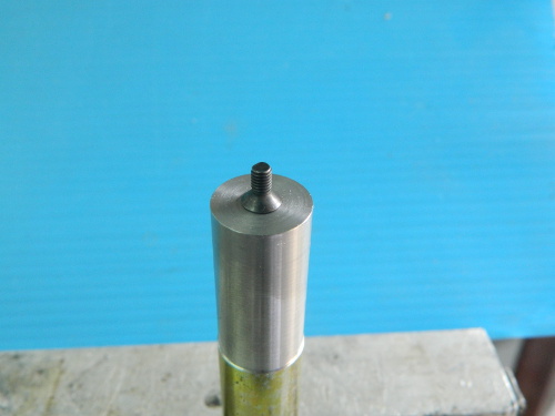
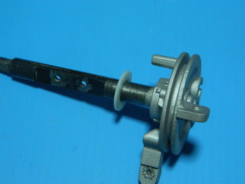
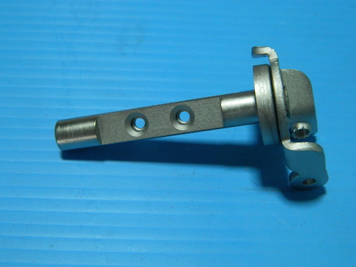 The Keihin shafts had what appears to be a teflon coating but as you can see in this image I lightly
polished the shafts and had the entire part Nickel plated. This added approximately 0.015 mm to the
diameter (from 7.850 to 7.865). This creates no problem for shaft clearance. If your coating is still in
good condition you may be able to get just the ends plated.
The Keihin shafts had what appears to be a teflon coating but as you can see in this image I lightly
polished the shafts and had the entire part Nickel plated. This added approximately 0.015 mm to the
diameter (from 7.850 to 7.865). This creates no problem for shaft clearance. If your coating is still in
good condition you may be able to get just the ends plated.
|
Method 1
 You need to prepare each butterfly and its matching shaft. Clean the gum off the butterfly with some steel wool and then use some 600 wet and dry to just run over the centre where the shaft sits. Don't sand off the number that you marked previously. Finally use the sandpaper to run through the shaft to remove any burrs and trial fit the butterfly. |
 Now use your Dremel with a fine cutoff wheel to slot your screws. Take the slot down until it almost touches the shaft. You can also shorten the screws a little if you have a small bike. The larger carb bodies that are used on the big bikes have thicker butterflies and hence need the full 6mm length. Repeat with the other three shaft assemblies. |
 This tool is made from a 2mm hex key that is epoxied into a piece of steel rod. The purpose is to support the screw and shaft whilst staking the screws. Of course use whatever suits the screws that you are using. For Torx use a #10. |
 And this just shows how the screw sits on the tool. |
 This is how the staking is performed. Of course the shaft assembly will be fitted to the carburettor. This image is just to make it clear how the tool supports the screw and shaft while the screw is staked. |
 I use 3 successive sizes to spread the screw. Don't try this with the rubbish mild steel screws that you buy from your local hobby shop, they will most likely split. |
Method 2
 In this method you drill the screws first. I used a 1.6mm drill for this task |
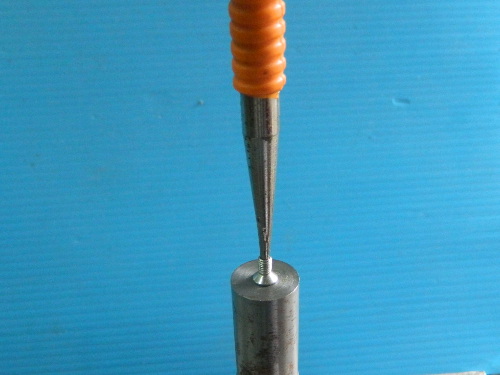 ... and then use a small centre punch to expand the screw after fitting. Of course the shaft assembly will be fitted to the carburettor. This image is just to make it clear how the tool supports the screw and shaft while the screw is staked. |
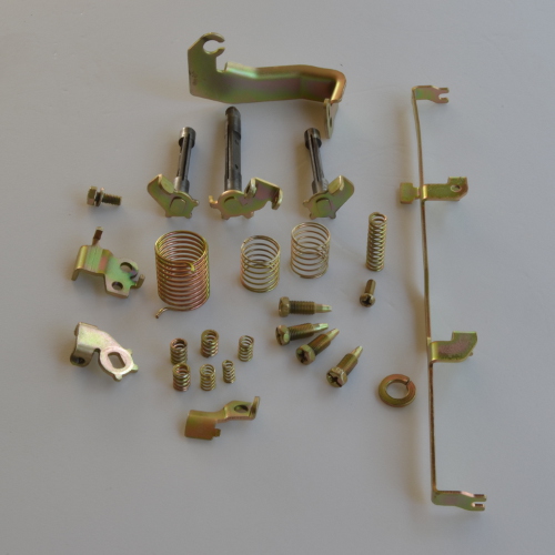
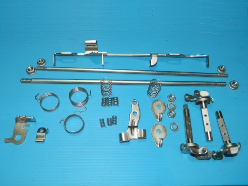
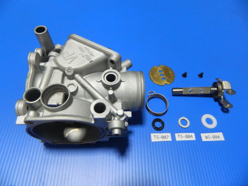
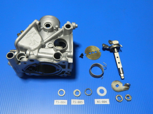
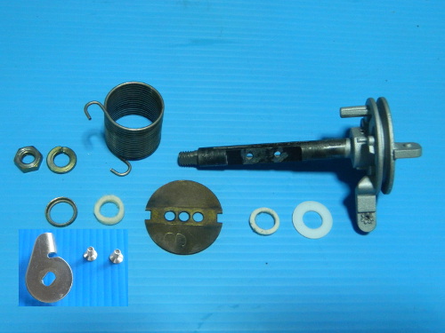
 Parts to be used for carburettor 1. |
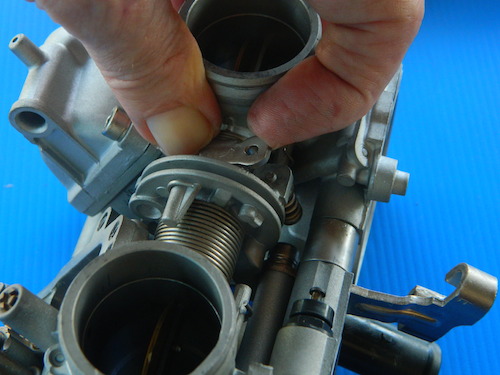
 First things first, and that means to trial fit the shaft into the carb and finally the shaft into the carb with the butterfly inserted. The shaft should rotate freely with no stiction at all. |
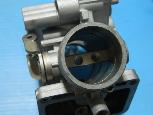
 Then fit the butterfly and gently jiggle it into position and lightly fit the screws so that when you hold the throat up to a source of light with the butterfly closed you cannot see any light. Of course a few photons sneaking through is acceptable. Now remove the butterfly and shaft. |
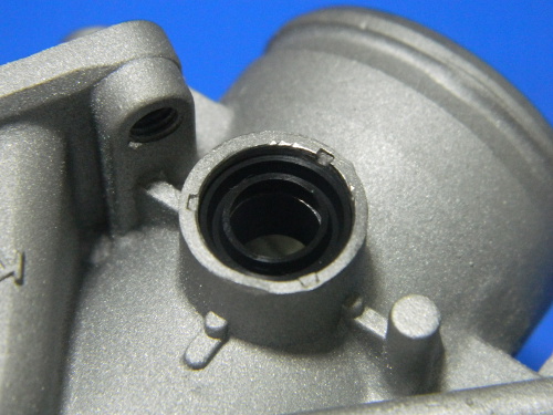
Now it is time to fit the seal (TS-007). Apply silicone to the outside edge of the seal to bond it to the
housing, and allow time for it to set. You can leave this step until after you have the shaft fitted if you
prefer. It appears to be reversed compared to what an oil seal looks like when fitted because
the low pressure is inside the carb.
|
 Now grease the felt seal (TS-004) and fit into the recess. We are recommending to grease the felt seal because that is what is usually done with felt seals. It is not recommended in Keihin's Bumper Guide to Carb Rebuilding because there is no such thing. Japanese companies do not want you to rebuild anything. They want you to buy a new motorcycle every three years like they do. |
 Fit the teflon washer (WS-004) to the shaft as shown. Your OEM washer is not made of teflon, it is nylon, we chose Teflon because we wanted to. If you want to use your old nylon version then you are free to do so. |
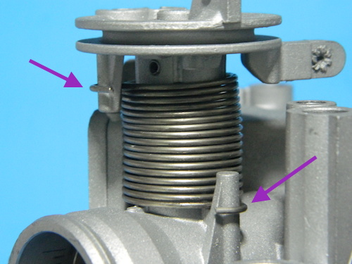
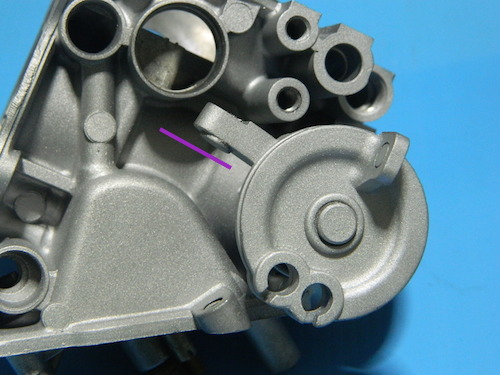
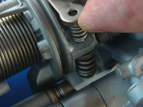
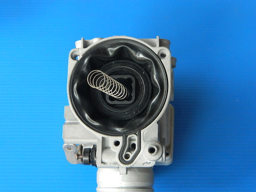
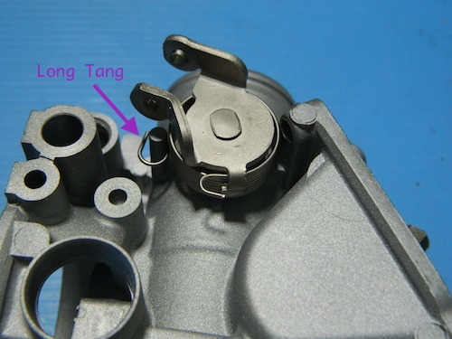 Now fit the spring onto the shaft and the shaft into the body with the longer tang hooked to the carb body as shown. |
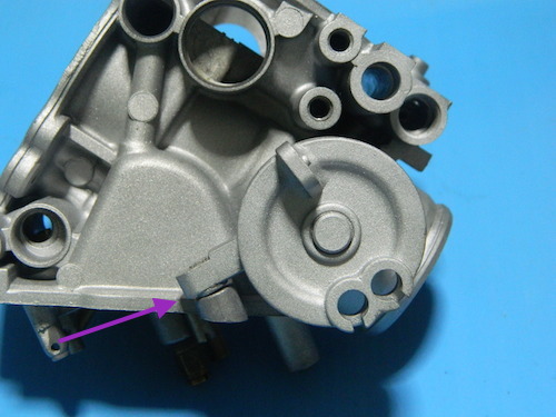
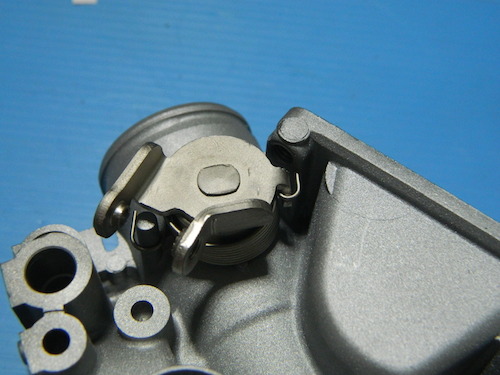 Now with both tangs of the spring hooked in their respective places, pull the shaft out about 5mm and rotate in a clockwise direction until it matches the position shown in the image. Then push the shaft assembly home. |
 Fit the butterfly as you did before. |
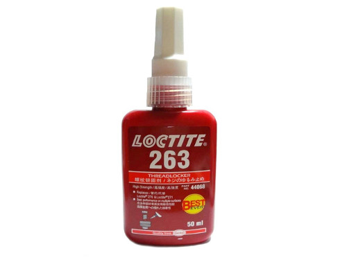 If you want to use some threadlocker then ensure that it is not passed its use by date. Most of these products have a limited shelf life and should be stored in a cool location. Now remove one of the screws so that you can apply threadlocker to the thread. |
 It is important to only apply the threadlocker to the thread and ensure that you do not spread over the countersunk part of the screw. I usually use another screw to roll the threadlocker around the thread ( fortunately all LiteTek kits come with a spare screw). Any excess can be wiped off with a cotton tip. |
 We recommend a 1/4 drive screwdriver handle for this task. This will reduce the risk of over tightening. If you are using hex socket screws then you need a 2mm hex bit, and if you are using Torx screws then you need a #10 socket. Do not use keys for this task as they are often poorly made. |
 Fit the screw, support it on Support Bar 1 (see the disassembly section), and tighten securely. Repeat the process with the other one. Now stake as shown above in the staking section. |
 Done. |
 Parts to be used for carburettor 4 (note the narrower spring). Being the other outside carb, just repeat the steps as per carb 1 |
 ... and done. |
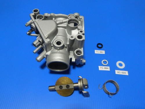
 Parts to be used for carburettor 2. Note the two different felt seals used. |
 Do a mock assembly of the shaft and butterfly as before. |
 This is the metal seal cap and TS-005, which is thicker than TS-004, |
 .. and it fits to the RH side of carb 2, which has the deeper recess. |
 Grease your seal and fit it into the cap. Then tap the assembly into the recess until flush. Now your teflon washer and spring onto the shaft as before. |
 Then on the other side grease and fit the TS-004 felt seal. |
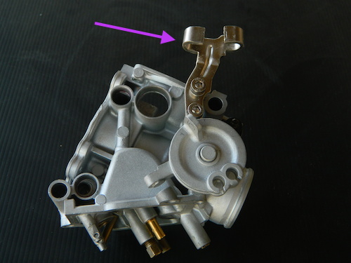
 Fit the throttle tang. Note how, like the others, its axis directs towards the top of the carb. |
At this stage the butterfly is not fitted so no chance of doing any damage. Secure the tang and tighten the nut. You can use some threadlocker if you want but first you will have to clean the grease from the threads. |
 As before, fit your butterfly. In this pic you can see we used the stainless steel Torx screws. They were staked using 'Method 2' described above. |
 Carb 3 is easily identified by the mounting bracket for the cable. |
 Parts to be used for carb 3. |
 As before, trial fit the shaft and butterfly assemly. |
 Then proceed to fit the capped seal as before, |
 Grease the thinner felt seal, TS-004, and fit on the other side. |
 Plastic washer fits over shaft. |
 Note how the spring tangs fit. |
 And the shaft will be sitting in this position before you tension the spring. |
 To tension the spring pull the shaft out just enough to allow it to clear the body and rotate in a clockwise direction until the stop rests in the correct position. |
 Then fit the tang, spring washer and nut to the other side and tighten by holding the tang as described above. Finally, fit your butterfly as you have done previously. If you have got this far then the worst is over. |
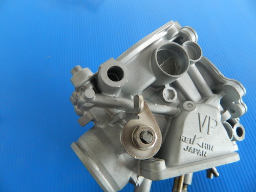
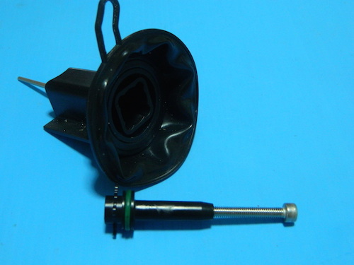
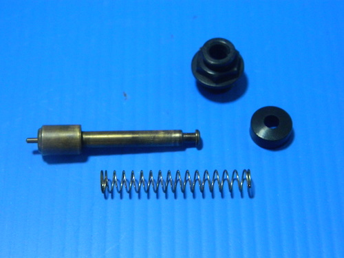 Choke plunger assembly parts. |
|
 Lubricate the lip of the new seal with some rubber or silicone grease, assemble and fit. |
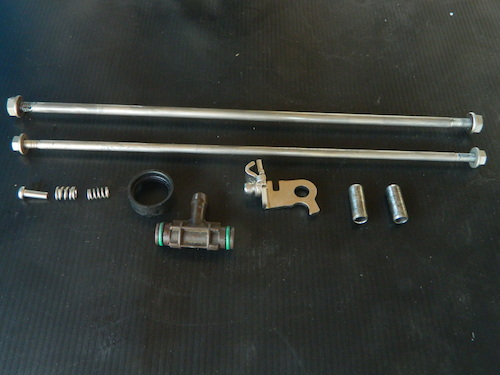
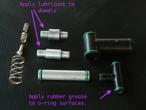 These are the parts that you will need to assemble carb 3 to carb 4. Because this is where the throttle cable actuator is located, it is the widest section with the widest parts. Test fit all parts and prepare surfaces until they are an easy fit by hand. Then lubricate the parts as indicated. |
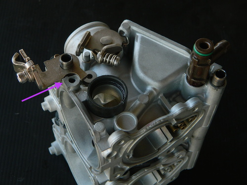
 First step is to attach the throttle cable bracket to carb 3. |
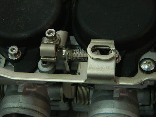
 Now fit the throttle synchronization screw and spring to the tang on carb 4. This spring has the larger diameter of the two. Note the button head socket screw that you won't have unless you bought that kit from us, and no, you can't buy them from China, eBay, or your local hardware store. |
 Now fit the parts to carb 3 as shown. The longest dowel fits to the rear. You should be able to fit them together by hand. If there is any resistance it will be because one of your fittings is misaligned. |
 You can fit the other throttle synch spring now or later. First, rotate the throttle mechanism |
 ... and fit. |
 You can hold the two together with a cable tie if they are prone to separating. |
 Onto carbs 1 & 2. These are the parts you need. The dowels have to be polished, replaced or whatever it takes to get them to be an easy fit into your carb bodies. You may in fact have to ream the bodies to achieve this. |
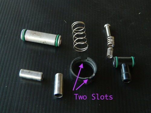
 Fit the parts to carb 1 and don't forget the throttle screw and spring. The rubber sleeve fits with the slots towards the body of carb 1. As before lubricate the parts. |
 If you have done a good job on the dowels it will be easy to join them. |
 Now to put the two halves together. These are the parts. Same as before, prepare the fit, (especially the dowels) and lubricate everything including the threaded rods. |
 And fit to the carb side as shown. Note the choke cable bracket. |
 Finally put the two halves together and fit the threaded rods. The small diameter assembly rod fits at the rear. Congratulations, now go and have a beer. |
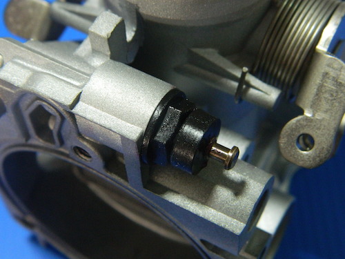
 Location of Needle o-ring. Note small internal spring and screw used to pull the assembly from the slide. |
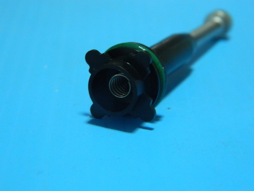 As always, lubricate the o-ring with some rubber or silicone grease, assemble and fit. |
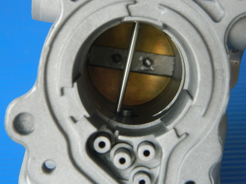 As you fit the slide assembly into the body, position the tip of the needle to the bore of the emulsion tube. This image shows how NOT to do it. |
 And this is how it should look. |
 Now work the diaphragm into its recess so its sits flush and does not pop out. |
 And fit the cap. |
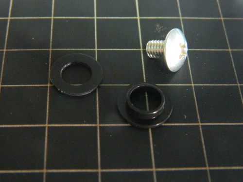 The choke actuating arm is held in place by two screws (M4 x 6) that sandwich the arm between two plastic washers. |
 Place the shouldered washers into position first. |
 Then slide the arm over the 4 plungers and rotate it up an over the plastic washer. |
 Then fit the plain plastic washer on top. |
 Then fit both screws. Some threadlocker is advisable for these. |
 Finally the return spring assembly can be fitted. This spring appears to be completely useless but you never know, maybe some pedantic judge at a bike show will deduct points for missing said useless spring. |